


77912-21 Network IC
77912-21 Network IC
Regular price
Rs.250.00 PKR
Regular price
Sale price
Rs.250.00 PKR
Shipping calculated at checkout.
Quantity
Couldn't load pickup availability
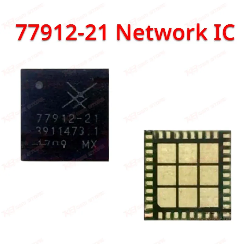
The 77912-21 Network IC is the SKY77912-21 Tx-Rx front-end module from Skyworks, built for quad-band GSM/GPRS/EDGE handsets with dual-band TD-SCDMA and TDD LTE Band 39 support. It packs the power amplifier, ten TRx antenna switch ports, and a directional coupler into one 5.5 x 5.3 x 0.8mm package, controlled over MIPI RFFE. On your repair bench, this is the go-to network IC for Samsung Galaxy J7 (2016) and J5 (2016) boards showing no network, no service, or weak signal faults. Genuine part number match, verified pinout-compatible replacement for board-level network circuit repair.
⚖️ Weight: 0.01 kg
SKU:MST-IC-272
- Safe & Secure Payment
- Fast Delivery
- WhatsApp Support


Description
FAQ
What is the product name?
The product name is the 77912-21 Network IC.
What is the brand of this product?
The brand of this product is Skyworks Solutions.
What is the model of this product?
The model of this product is SKY77912-21.
What is this product used for?
This product is used to restore network and signal function on boards with no service, weak signal, or network drop faults.
Which devices are compatible with this product?
This product is compatible with the Samsung Galaxy J7 (2016) / SM-J710 and Galaxy J5 (2016) / SM-J510 / SM-J510FN.
Who should use this product?
This product is suitable for mobile repair technicians, repair shops, service centers, and professional users.
Does this IC support both GSM and TD-SCDMA/LTE bands?
Yes, it covers quad-band GSM/GPRS/EDGE on the low band and DCS, PCS, TD-SCDMA bands 34/39, and TDD LTE band 39 on the high band, all through one module.
What causes this network IC to fail, and can reflow fix it?
Failure usually follows liquid damage, board flex from a drop, or heat stress from earlier rework; a cold joint sometimes resolves with a controlled hot air reflow, but a cracked die needs a full chip replacement.