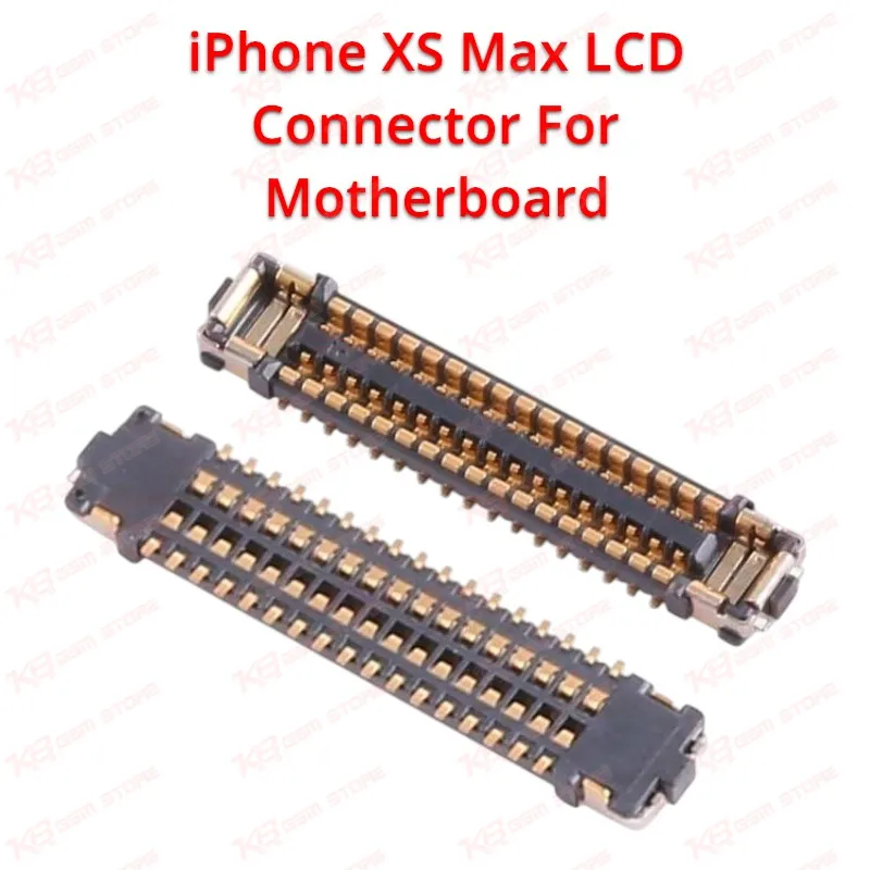
The iPhone XS Max LCD FPC connector, identified by its OEM part reference J5700, is a 34-pin surface-mount connector soldered directly onto the motherboard to establish the physical and electrical link between the LCD display assembly and the logic board circuitry. When this connector cracks, lifts, or corrodes from liquid damage, the phone typically shows symptoms such as a blank display with the device still powering on, a black screen with backlight visible, vertical or horizontal lines across the screen, flickering, or intermittent display dropout when the phone is moved or the flex cable is pressed. In many of these cases the touch function and other board circuits continue to operate normally, which points technicians toward the display connector rather than a full logic board or LCD screen fault, making this a targeted and cost-effective repair instead of a full motherboard replacement. Because the connector sits on the board side rather than the flex cable side, replacement is a board-level micro-soldering task rather than a simple cable swap, and it requires the damaged connector to be removed with hot air, the pad cleaned of old solder and flux residue, and the new J5700 connector realigned and reflowed with precision to avoid bridging the fine 34-pin pitch. This type of repair sits within the broader mobile phone repair workflow at the intersection of display diagnostics and PCB-level rework, since a technician must first isolate the fault to the connector itself through visual inspection under a microscope and continuity testing before committing to desoldering, given that the pins are closely spaced and easy to damage with imprecise heat application. For a repair shop or service center working on iPhone X-series boards, having this connector in stock supports faster turnaround on common accident scenarios like drop damage, liquid exposure, or previous unsuccessful screen replacements that left the on-board pins bent or lifted. The connector is manufactured to match the original footprint, pin count, and pitch of the factory component, which means it seats correctly against the existing solder pad without requiring modification to the board layout, and proper reflow temperature control during installation preserves the integrity of surrounding components such as adjacent ICs and passive elements on the same board region. Technicians handling this repair typically pair the connector with a hot air rework station set to a controlled temperature profile, flux to aid solder flow and prevent oxidation, and either a microscope or high-magnification loupe to confirm pin alignment before and after reflow, since misalignment at this stage is one of the most common causes of a failed repair or a display that partially works after reassembly. This connector is also relevant to technicians troubleshooting boot loop or hang-on-logo symptoms that persist after a screen swap, since a damaged on-board connector can sometimes present similarly to a display assembly fault, and ruling it out with a known-good connector or continuity check narrows the diagnosis before further disassembly. Stocking this part alongside related board-level components such as touch FPC connectors, backlight connectors, and other J-series on-board connectors for the X-series lineup allows a workshop to cover the full range of display-related motherboard faults for this chipset generation without depending on a full donor board. Given the precision required, this connector is best suited to technicians already experienced in BGA-level or fine-pitch soldering rather than beginners attempting their first board-level repair, and careful ESD handling is recommended throughout removal and installation to protect the surrounding motherboard circuitry from static damage.